A requirement for the QNX network driver we recently wrote was to add support for outputting a pulse-per-second signal, similar to the Linux PTP_PEROUT_REQUEST ioctl. We added support to the driver by creating a new IOCTL command and a simple utility program to issue the command to enable or disable the PPS output. This is described in more detail here: QNX network driver custom ioctls .
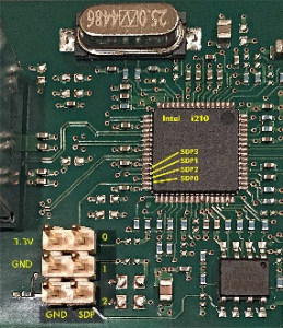
The target system we used for testing was a generic Intel 64-bit platform with the QNX 7 x86_64 BSP. The target system provided an on-chip Intel i219 network interface which was the default boot interface. The Intel i219 does not have hardware support for PTP so we fitted a Intel i210 PCIe card to a free slot on the motherboard. We used the i210 as a reference for the PTP support we added to the driver we wrote. This worked well for the standard PTP protocol testing so we decided to add PPS support to the e1000 driver.
The Intel i210 has a number of GPIO pins, known as SDP pins, which can be configured to output a “time triggered event”. This is described in detail in section 7.8.3.3 Target Time of the Intel i210 reference manual.
The two target time registers TRGTTIML/H0 and TRGTTIML/H1 enable generating a time triggered event to external hardware using one of the SDP pins according to the setup defined in the TSSDP and TSAUXC registers (see Section 8.15.13 and Section 8.15.25). Each target time registers is structured the same as the SYSTIML/H registers. If the value of the SYSTIML/H is equal or larger than the value of the TRGTTIML/H registers, a change in level or a pulse is generated on the matched SDP outputs.
There are 3 ways this can be done but the simplest method is to use the configuration described in section 7.8.3.3.3 Synchronized Output Clocks on SDP Pins. This does not require any further software intervention once it has been configured. As the name suggests, in this mode a programmable clock is synchronised to the PTP system clock and the clock is output on a SDP pin.
In fact, this is the approach taken by the Linux igbe driver to implement the PTP_PEROUT_REQUEST ioctl.
A 1 Hz output is produced by setting the programmable clock period to 500 ms. At the end of the clock period the signal level on the SDP pin toggles, which produces a 1 Hz square wave. This becomes a PTP pulse-per-second output by setting the target time register to the next whole number of seconds the PTP system time will reach. When the system time hits the target time the level on the SDP changes and the target time register is incremented by the clock period (500 ms).
To add support for the PPS enable we added the following to e1000_ptp_ioctl():
        case PTP_ENABLE_PPS:
            e1000_ptp_pps_enable(i82544);
            return EOK;
            break;

        case PTP_DISABLE_PPS:
            e1000_ptp_pps_disable(i82544);
            return EOK;
            break;
The work was done by the following:
/*
 * Enable 1 Hz output on SDP0 synchronised to seconds transition of PTP clock
 * using method in section 7.8.3.3.3 Synchronized Output Clock on SDP Pins.
 */
static void e1000_ptp_pps_enable(i82544_dev_t *i82544)
{
    uint32_t val;
    struct e1000_hw *hw = &i82544->hw;

    /*
     * Set up SDP0 as an output pin
     */
    val  = E1000_READ_REG(hw, E1000_CTRL);
    val |= (1U << 22);
    E1000_WRITE_REG (hw, E1000_CTRL, val);

    /*
     * Assign this pin to output FREQ0
     */
    val  = E1000_READ_REG(hw, E1000_TSSDP);
    val &= ~E1000_TSSDP_AUX0_TS_EN;
    val &= ~E1000_TSSDP_AUX1_TS_EN;
    val &= ~E1000_TSSDP_TS_SDP0_SEL_MSK;
    val |= E1000_TSSDP_TS_SDP0_SEL_FQ0;
    val |= E1000_TSSDP_TS_SDP0_EN;
    E1000_WRITE_REG (hw, E1000_TSSDP, val);

    /*
     * Disable the output clock
     */
    val = E1000_READ_REG(hw, E1000_TSAUXC);
    val &= ~(E1000_TSAUXC_ENABLE_TARGET_TIME0  |
             E1000_TSAUXC_ENABLE_CONFIG_CLOCK0 |
             E1000_TSAUXC_START_CLOCK0);
    E1000_WRITE_REG (hw, E1000_TSAUXC, 0);

    /*
     * Set up the clock frequency
     */
    uint32_t half_cycle = 500000000U;         /* 500 ms half cycle */

    E1000_WRITE_REG (hw, E1000_FREQOUT0, half_cycle);

    /* Get the current PTP time */

    ptp_time_t time;

    e1000_ptp_get_time (i82544, &time);

    /*
     * Start the clock in 2.5 seconds
     *
     * The initial clock output is low. Adding 500ms to the start time
     * gives a rising edge when there is a whole number of seconds.
     */
    E1000_WRITE_REG (hw, E1000_TRGTTIMH0, time.sec + 2);
    E1000_WRITE_REG (hw, E1000_TRGTTIML0, half_cycle);

    /*
     * Enable the output clock
     */
    val  = E1000_READ_REG(hw, E1000_TSAUXC);
    val |= E1000_TSAUXC_ENABLE_CONFIG_CLOCK0 |
           E1000_TSAUXC_START_CLOCK0;
    E1000_WRITE_REG (hw, E1000_TSAUXC, val);
}

static void e1000_ptp_pps_disable(i82544_dev_t *i82544)
{
    uint32_t val;
    struct e1000_hw *hw = &i82544->hw;

    /*
     * Disable the output clock
     */
    val = E1000_READ_REG(hw, E1000_TSAUXC);
    val &= ~(E1000_TSAUXC_ENABLE_TARGET_TIME0  |
             E1000_TSAUXC_ENABLE_CONFIG_CLOCK0 |
             E1000_TSAUXC_START_CLOCK0);
    E1000_WRITE_REG (hw, E1000_TSAUXC, 0);

    /*
     * Remove clock from pin
     */
    val  = E1000_READ_REG(hw, E1000_TSSDP);
    val &= ~E1000_TSSDP_TS_SDP0_SEL_MSK;
    val &= ~E1000_TSSDP_TS_SDP0_EN;
    E1000_WRITE_REG (hw, E1000_TSSDP, val);
}
The generic x86_64 BSP does not include the e1000 driver source. However, it is included in the Gordon Ridge BSP. The changes above were added to that driver and then the driver was rebuilt.
The following was added to the generic BSP build file to include the modified e1000 driver shared library object:
devnp-e1000-pps.so=${ECLIPSE_WORKSPACE}/Intel-x86_64-APL-abl/src/hardware/devnp/e1000/x86_64/dll/devnp-e1000.so
The modified driver was now included in the QNX kernel image on our target system.
After startup the i210 is managed by the standard e1000 driver, not the modified driver with the PTP changes above. On our target it came up as device wm1. To use our modified driver the device had to be detached from the default network stack and attached to a new network stack instance (using multliple network stacks is described here: QNX Network Driver Development. Moreover, it was necessary to set the driver-specific PTP option flag to enable hardware support for PTP in the modified e1000 driver.
# ifconfig wm1 destroy
#
# io-pkt-v6-hc -i3 -ptcpip prefix=/sock3
# mount -Tio-pkt3 -o vid=0x8086,did=0x1533,ptp devnp-e1000-pps.so
# SOCK=/sock3 ifconfig wm0 192.168.204.8
To use the new i210 driver, the PTP daemon was started as follows:
# SOCK=/sock3 ptpd -g -C -b wm0 -L
   (ptpd info)     14:13:19.394050  (___)
   (ptpd info)     14:13:19.394050  (___)  Starting ptpd2 daemon with parameters:      ptpd -g -C -b wm0 -L
   (ptpd info)     14:13:19.400050  (___)    Info:    No ptpd daemons detected in parallel (as expected)
   (ptpd info)     14:13:19.405050  (___)    Info:    No ntpd daemons detected in parallel (as expected)
   (ptpd info)     14:13:19.406050  (___)    Info:    Startup finished sucessfully

# Timestamp, State, Clock ID, One Way Delay, Offset From Master, Slave to Master, Master to Slave, Drift, Last packet Received
2019-07-24 14:13:19.406050, init
   (ptpd notice)   14:13:19.406050  (init)  hw time support 1
   (ptpd notice)   14:13:19.407050  (init)  setPtpTimeFromSystem to TAI: 1563977599s 406050119ns
   (ptpd info)     14:13:19.439050  (init)  refreshed IGMP multicast memberships
   (ptpd info)     14:13:19.439050  (init)    now in state PTP_LISTENING
The PPS output was enabled using our new PTP utility as follows:
# SOCK=/sock3 pps-ctl -d wm0 -p 1
wm0: PPS enabled
The PPS signal was output on SDP0. We were using a HP i210-T1 card, which has a 6-pin header on it. The following picture shows the signals on this header:
The SDP0 was connected to a scope along with the PTP master PPS signal. The PPS master was a Linux system with an i210 configured to output a PPS signal on SDP0. The PPS signal from master and slave targets was captured on a dual channel oscilloscope. The master PPS signal was used to trigger the capture.
Following synchronisation of the slave the following trace was seen after several hours:
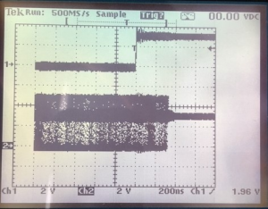
The lower signal is the output from the slave i210 on the QNX target system. The trace persistence shows the jitter in the QNX slave PTP clock, which is about 1.4 microseconds.